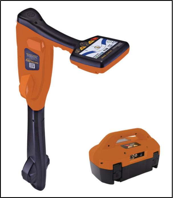
Figure 6 t5000-3 transmitter and receiver
Instrument: t5000-3 color screen intelligent pipeline instrument
Signal output part: transmitter, direct connection, coupling clamp, LCC module
Direct connection: direct connection signal output line, used when finding the route of power cut cable
Coupling clamp: clamp method signal output line, used when finding live cable path
LCC module: it can isolate the AC voltage of 480v and below, and cooperate with transmitter to connect the AAC Cable with direct connection method, and find the live low voltage cable path and transmission cable path.
picture
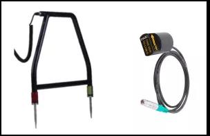
Figure 7 transmitter accessories
Receiving signal part: receiver, stethoscope, A-frame

Figure 8 receiver accessories
Stethoscope: it can be used in cooperation with receiver to identify the ABC Cable live and find the target cable from multiple cables;
A-Frame: it can be used in combination with receiver to accurately locate the fault point of buried cable, and the use method is step voltage method.
3、 Transmitter wiring method
1. direct connection method
It is suitable for finding the route of power cut cable, with high current and strong signal. The transmitting signal is injected into the primary core through the direct connection, and the test phase core at the end of the cable is grounded manually. The primary core and the earth constitute the test circuit, as shown in Figure 9 below.
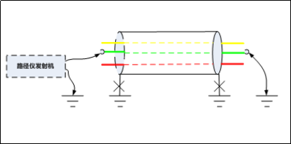
Figure 9 schematic diagram of direct connection
Tips:
1. the signal can not be transmitted between phases (short circuit at the end) and the test circuit can not be formed by phase. Because the current signal is in the opposite direction, the magnetic field signal is offset. The receiver is essentially the received loop magnetic field signal, and the signal will not be received;
2. the armored ground on both sides of the cable shall be removed, otherwise the current signal transmitted will be transmitted back from the armor, which will also offset the magnetic field signal;
3. in a word, the test circuit shall be one-way and only circuit.
If the cable circuit is connected incorrectly, such as poor grounding, phase sequence error, etc., the transmitter has no output current or low output current, and the “indicating square” is blank, as shown in Figure 10 below. If the circuit is connected correctly, the output current of transmitter can reach 25mA, and the “indicating square” turns black, as shown in Figure 11 below.
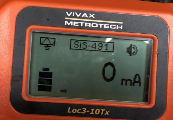
Figure 10 display of transmitter with wrong circuit connection
2. clamp method
It is suitable for finding the route of stop and live cable, with small current and weak signal. The transmission voltage signal is induced to the high voltage cable armour or low voltage cable zero line through coupling clamp. As shown in Figure 12, since both ends of the cable are armored or zero wire are grounded, there will be stable current signal naturally.
Tips:
1. the same point between direct connection method and clamp method is that the magnetic field signal is generated by unidirectional stable current circuit. The difference is that direct connection method transmits signal in cable core through direct connection, and clamp method is used to couple transmission signal in cable armour or zero line through clamp coupling;
2. clamp method is relatively weak in signal application, and direct connection method is preferred for power cut cable;
3. for high voltage single core live cable, direct connection method can be used to find the path in aluminum sheath. The use of clamp method and direct connection method should be reasonably selected in combination with the grounding mode of aluminum sheath.
3.1 380V cable test method
380V power off cable:
① The direct connection method of conductor is shown in Figure 9, and the one-phase core is selected as the test phase, and the end of the line core is grounded with corresponding phase core, and the zero line grounding at both ends is removed. The fire line and terrain are single-phase and unique circuit;
② Zero line direct connection method: remove zero line grounding at one end of cable, and keep zero line grounding at the other end. The direct output line is connected to the suspended zero line, and the zero line and terrain are single-phase and unique circuit, as shown in Figure 13 below;
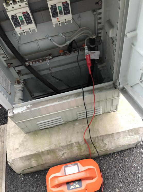
Figure 13 zero wire direct connection
③ Clamp method, as shown in Figure 12, the output clamp is directly stuck in the cable body or cable zero line, and the signal circuit is formed between the zero line and the ground. Note: at this time, the zero line at both ends of the cable should be grounded.
380V live cable:
① Clamp method, the wiring is the same as above;
② LCC, live direct connection, transmitter on the user side directly outputs the signal on the live fire line through LCC module. For 380 power supply low voltage power supply system, neutral point of transformer in the station area is directly grounded. At this time, the live fire line and the ground form a loop. Note: this method can only be used in the user side wiring, and find the cable path from the power side, The site case is referred to the above official account.
3.2 10kV cable test method
10kV power off cable:
① The direct connection method of conductor is shown in Figure 9, and the one-phase core is selected as the test phase, and the end of the corresponding phase wire core is grounded, and the armored grounding at both ends is removed. The conductor and terrain are single-phase and unique circuit;
② Armor direct connection method: remove the armored grounding at one end of the cable, and keep the armored grounding at the other end. The direct output line is connected to the suspended armored lead wire, and the armor and terrain are single-phase and unique circuit, as shown in Figure 14 below;
③ Clamp method, as shown in Figure 12, shows that the output clamp is directly stuck on the cable body or cable armored ground wire, and the signal circuit is formed between the armor and the ground. The clamp connection demonstration is shown in Figure 15 below.
10kV live cable:
Clamp method, same as above.
3.3 test method of 110kV cable
110kV power off cable:
① Direct connection of conductors, as above;
② For the direct connection method of aluminum sheath, the grounding mode of aluminum sheath shall be referred to. For the single end grounded cable section of aluminum sheath, the direct connection signal of aluminum sheath coaxial cable conductor shall be directly connected at the protective grounding box; For the cross connected cable section with aluminum sheath, the conductor or shielding direct connection signal of aluminum sheath coaxial cable shall be conducted at any cross interconnection box.
110kV live cable:
① For the cable section with single end grounding of aluminum sheath, open the protective grounding box or cross connected box with no grounding end. First, use multimeter to measure the induced voltage of the aluminum sheath. If the induction voltage is less than 25V (t5000-3 fuse fuse fuse fuse fuse fuse voltage), direct connection method can be directly used for aluminum sheath, as shown in Figure 16 below;
② If the induction voltage of aluminum sheath without grounding terminal exceeds 25V, LCC module incoming voltage shield shall be used and the live direct connection method shall be used for test;
③ Clamp method: because the aluminum sheath of cross connected large section is directly grounded at both ends, although the cable is transposed, the overall aluminum sheath still forms a circuit with the ground. Therefore, clamp method is only applicable to the path finding of 110kV cable section cross connected by aluminum sheath, and clamp the clamp directly on the coaxial cable at the cable body or any grounding box, as shown in Figure 18 below.
Tips:
1. when finding the path of 110kV cable live, it is better to search by sections according to aluminum sheath, and apply signal from the ground end to find the cable path to the grounding end;
2. for the cable section with no grounding at the direct grounding end of one end of aluminum sheath, the clamp method signal is weak. At this time, the output power of transmitter shall be increased and the output frequency shall be adjusted to test. It is recommended to use direct connection method or live direct connection method for finding out the ungrounded end;
3. because 110kV single core cable will generate induction voltage on aluminum sheath, if clamp is directly stuck on cable body, inductive voltage will also be generated in clamp. At this time, if clamp jaws are completely closed, circulation will be formed on clamp coil, and clamp will be burned by heating, that is, paper sheet shall be pad for closing jaw, as shown in Figure 19 below.
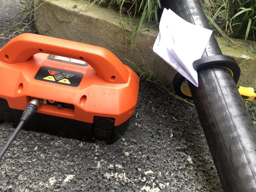
Figure 19 jaw treatment of clamp method when using the body
